NJR2-D Series Soft-Starter
NJR2-D Series Soft-Starter
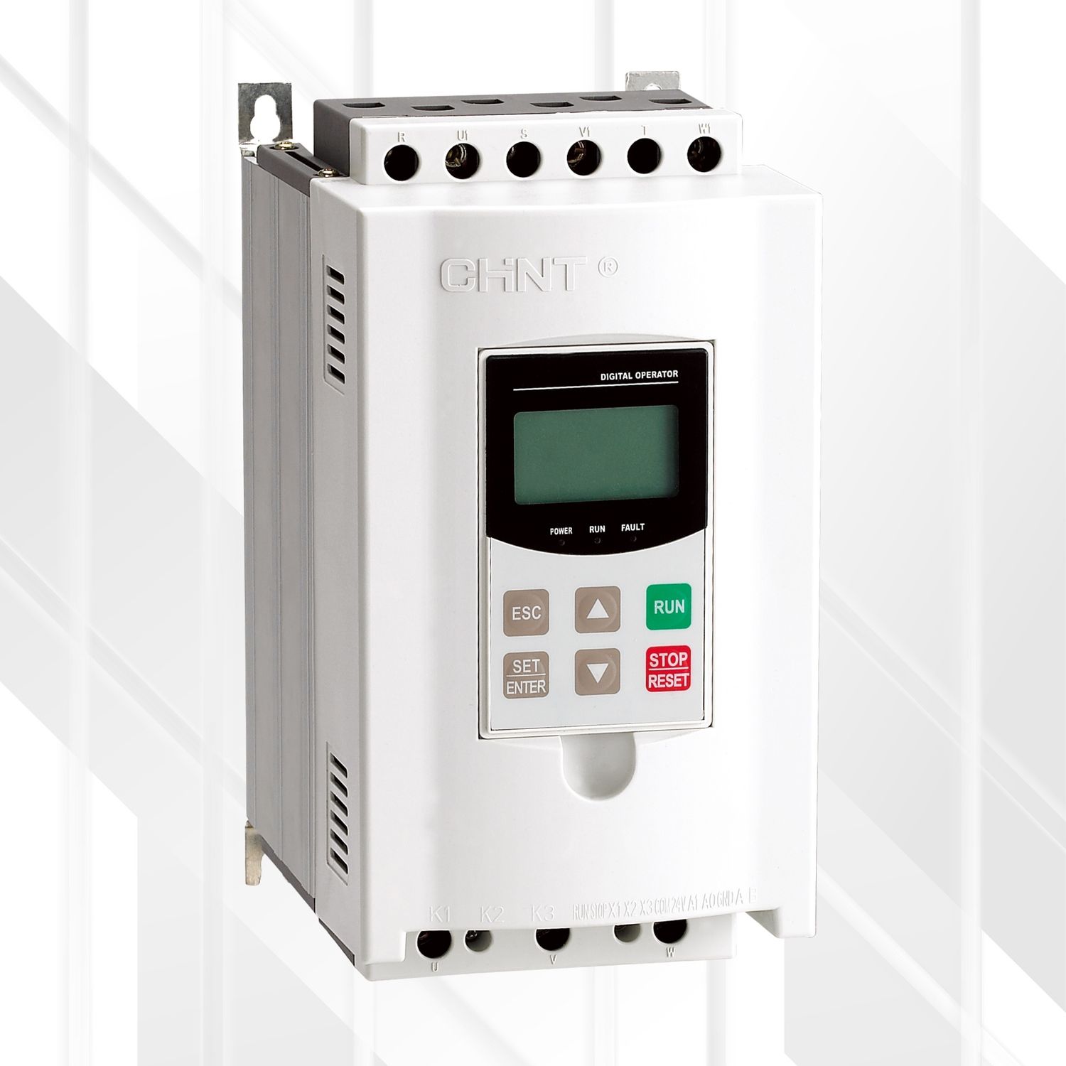
- The CHINT NJR2-D Series Soft-Starter is an advanced solution for the smooth and controlled starting and stopping of three-phase AC asynchronous squirrel cage motors.
- Engineered with dual-CPU control technology, it effectively limits starting current and voltage, reducing mechanical and electrical stress on motors and connected equipment.
- This prolongs service life and enhances operational reliability. The NJR2-D series stands out with its comprehensive protection features, user-friendly interface, multiple starting modes, and robust design, making it an ideal replacement for traditional starting methods like star-delta, auto-transformer, or direct-on-line starters, especially in applications where high starting torque is not a primary requirement.
Features
- Advanced Control: Utilizes dual-CPU control and SCR (Silicon Controlled Rectifier) modules for precise and reliable motor management.
- Smooth Start/Stop: Provides gradual acceleration and deceleration, minimizing mechanical shock and electrical surges.
- Multiple Starting Modes: Includes Current Limiting, Voltage Ramp, Current Ramp, Step Voltage + Current Limiting, Step Voltage + Voltage Ramp, and Double Closed-Loop modes to suit diverse load applications.
- Comprehensive Motor Protection: Offers a wide array of protection functions:
- Overload protection
- Input and Output phase failure protection
- Load short-circuit protection
- Starting limiting overtime protection
- Over-voltage and Under-voltage protection
- Soft starter overheating protection
- Three-phase unbalance protection
- User-Friendly Interface: Features a large LCD screen for easy parameter setting, real-time monitoring, and fault diagnosis.
- Removable Keypad: Allows for convenient remote operation and configuration (up to 2m with extended lead).
- Enhanced EMC Design: Ensures high stability and anti-EMS interference for reliable operation in industrial environments.
- RS485 Communication: Supports Modbus RTU protocol for integration into automation systems, enabling remote control and monitoring.
- Fault Diagnostics: Records up to 9 past fault records for easy troubleshooting.
- Efficient Cooling: Natural air cooling. Select models (≤75kW) feature a patented all-aluminum design for superior heat dissipation.
- Bypass Contactor Control: Designed for use with an external bypass contactor, which is controlled by the soft starter's K1 relay.
- Wide Power Range: Suitable for motors from 7.5kW to 500kW (at 380V).
Benefits
- Increased Equipment Lifespan: Reduces mechanical stress on gears, belts, and couplings, and electrical stress on motor windings, extending the life of the motor and driven machinery.
- Reduced Downtime: Comprehensive protection features prevent motor damage and system failures, leading to higher operational availability.
- Energy Savings: Lowered inrush currents during startup can reduce peak demand charges and overall energy consumption.
- Improved Power Quality: Minimizes voltage sags and current surges on the power supply network during motor starting.
- Optimized Performance: Multiple starting modes allow tailoring the start-up characteristics to specific load requirements, ensuring efficient and smooth operation.
- Ease of Use & Maintenance: Intuitive LCD interface, removable keypad, and fault logging simplify setup, operation, and troubleshooting.
- System Integration: RS485 communication enables seamless integration with PLCs, SCADA systems, and other industrial control networks.
- Compact Design: Efficient cooling designs contribute to a smaller footprint.
In-Depth Technical Specifications
General Specifications:
| Feature | Specification |
|---|---|
| Product Series | CHINT NJR2-D Series Soft-Starter |
| Main Supply Voltage | Three-phase AC 380V ±15% |
| Main Power Frequency | 50Hz/60Hz (±2%) |
| Applicable Motor | Three-phase squirrel cage asynchronous motor |
| Control Technology | Advanced Dual-CPU Control, SCR Module Control |
| Starting Modes | Current Limiting, Voltage Ramp, Current Ramp, Step Voltage + Current Limiting, Step Voltage + Voltage Ramp, Double Closed-Loop |
| Cooling Mode | Natural Air Cooling |
| Protection Level | IP20 |
| Rated Insulation Voltage | 660V |
| Rated Impulse Withstand Voltage | 2kV |
| Pollution Degree | 3 |
| EMC Equipment Level | Class A (Industrial) |
| Starting Voltage (Initial) | 30%Ue ~ 70%Ue (Adjustable, Ue: Rated Voltage) |
| Start Limited Current | 50%Ie ~ 500%Ie (Adjustable, Ie: Rated Current) |
| Starting Frequency | Recommended: Less than 10 times per hour (load dependent) |
| Overload Protection Class | Level 2, Level 10A, Level 10, Level 20, Level 30 (Selectable) |
| Relay Outputs | Bypass Relay (K1), Programmable Relay (K2), Fault Relay (K3) - Contact Capacity 5A/250VAC |
| Communication Interface | RS485 (Modbus RTU Protocol) |
| Display | Large screen LCD |
| Keyboard | Removable (for remote operation up to 2m, order separately if extended lead needed) |
| Ambient Temperature | Operating: -10°C to +40°C. Derate by 2% current per 1°C increase for +40°C to +50°C. |
| Storage Temperature | -25°C to +70°C |
| Relative Humidity | < 95% (at 20°C ~ 65°C), non-condensing |
| Altitude | Up to 1000m without derating. Above 1000m, derate current by 0.5% per 100m increase (up to 3000m). |
| Vibration Resistance | Less than 0.5g |
| Certifications / Standards | IEC 60947-4-2, GB 14048.6 |
| Required Peripherals | External Bypass Contactor (NJR2-D is a basic type without internal bypass) |
Model-Specific Specifications (Power, Current, Dimensions, Weight):
(Note: Dimensions are Overall Width (B) x Overall Height (D) x Overall Depth (E) in mm, [Mounting Width (A) x Mounting Height (C) in mm])
| Power (kW) | Model | Rated Current (A) | Overall Dimensions (mm) (B x D x E) | Mounting Dimensions (mm) (A x C) | Net Weight (kg) | Figure Ref. (Datasheet) |
|---|---|---|---|---|---|---|
| 7.5 | NJR2-7.5D | 15 | 145 x 268 x 190 | 128 x 250 | 5 | Fig 5.1 / Group 1 |
| 11 | NJR2-11D | 22 | 145 x 268 x 190 | 128 x 250 | 5 | Fig 5.1 / Group 1 |
| 15 | NJR2-15D | 29 | 145 x 268 x 190 | 128 x 250 | 5 | Fig 5.1 / Group 1 |
| 18.5 | NJR2-18.5D | 36 | 145 x 268 x 190 | 128 x 250 | 5 | Fig 5.1 / Group 1 |
| 22 | NJR2-22D | 42 | 145 x 268 x 190 | 128 x 250 | 5 | Fig 5.1 / Group 1 |
| 30 | NJR2-30D | 57 | 145 x 268 x 190 | 128 x 250 | 5 | Fig 5.1 / Group 1 |
| 37 | NJR2-37D | 70 | 145 x 268 x 190 | 128 x 250 | 5 | Fig 5.1 / Group 1 |
| 45 | NJR2-45D | 84 | 145 x 268 x 190 | 128 x 250 | 5 | Fig 5.1 / Group 1 |
| 55 | NJR2-55D | 103 | 200 x 310 x 215 | 183 x 270 | 8 | Fig 5.2 / Group 2 |
| 75 | NJR2-75D | 140 | 200 x 310 x 215 | 183 x 270 | 8 | Fig 5.2 / Group 2 |
| 90 | NJR2-90D | 167 | 253 x 529 x 241 | 220 x 426 | 20 | Fig 5.3 / Group 3 |
| 110 | NJR2-110D | 207 | 253 x 529 x 241 | 220 x 426 | 20 | Fig 5.3 / Group 3 |
| 132 | NJR2-132D | 248 | 253 x 529 x 241 | 220 x 426 | 20 | Fig 5.3 / Group 3 |
| 160 | NJR2-160D | 300 | 253 x 529 x 241 | 220 x 426 | 20 | Fig 5.3 / Group 3 |
| 185 | NJR2-185D | 349 | 253 x 529 x 241 | 220 x 426 | 20 | Fig 5.3 / Group 3 |
| 220 | NJR2-220D | 404 | 293 x 564 x 253 | 240 x 464 | 25 | Fig 5.4 / Group 4 |
| 250 | NJR2-250D | 459 | 293 x 564 x 253 | 240 x 464 | 25 | Fig 5.4 / Group 4 |
| 280 | NJR2-280D | 514 | 293 x 564 x 253 | 240 x 464 | 25 | Fig 5.4 / Group 4 |
| 315 | NJR2-315D | 579 | 293 x 564 x 253 | 240 x 464 | 25 | Fig 5.4 / Group 4 |
| 355 | NJR2-355D | 630 | 444 x 752 x 250 | 360 x 616 | 52.5 | Fig 5.5 / Group 5 |
| 400 | NJR2-400D | 720 | 444 x 752 x 250 | 360 x 616 | 52.5 | Fig 5.5 / Group 5 |
| 450 | NJR2-450D | 810 | 444 x 752 x 250 | 360 x 616 | 52.5 | Fig 5.5 / Group 5 |
| 500 | NJR2-500D | 900 | 444 x 752 x 250 | 360 x 616 | 52.5 | Fig 5.5 / Group 5 |
(Dimensions and weights are grouped by physical size as per datasheet figures. Group 1 refers to models NJR2-7.5D to 45D, Group 2 for NJR2-55D to 75D, etc. Dimensions A, B, C, D, E as per catalog convention used for clarity.)
Ideal Use
- Pumps: Centrifugal pumps in water supply, wastewater treatment, irrigation.
- Fans & Blowers: HVAC systems, industrial ventilation, exhaust systems.
- Compressors: Air compressors, refrigeration units (where starting torque is moderate).
- Conveyors: Belt conveyors, screw conveyors (for smooth starting).
- Crushers & Ball Mills: Mining and material processing (consider load characteristics).
- General Industrial Machinery: Mixers, agitators, and other equipment requiring smooth motor starting.
- Industries: Metallurgy, petroleum, chemical, fire protection systems, mining, water supply, municipal engineering, food processing, cement, and petrochemical industries.
- Suitable for applications with ordinary squirrel cage three-phase asynchronous motors where reduced starting current and smooth acceleration are desired, and high starting torque is not the primary concern.
Layout

Layout Part Numbers:
-
Soft Starter
-
Heat Sink
-
Thyristor Module (or SCR Module)
-
Chassis / Enclosure
-
Mounting Plate
-
Crystal Oscillator
-
Resettable Fuse / Self-resetting Fuse
-
Buzzer
-
CPU Chip
-
Voltage Regulator Diode (Zener Diode)
-
Relay
-
External Control Terminals
-
Relay Output Terminals
-
CPU Control Board
-
Operation Panel / Control Panel
-
Cover / Lid
-
Power Driver Board
-
Varistor (Voltage Dependent Resistor - VDR)
-
Filter
-
Resistor
-
Pulse Transformer
-
High-Frequency Transformer
-
Field-Effect Transistor (FET)
-
Electrolytic Capacitor
Tips: Maximizing Performance and Longevity of Your NJR2-D Soft-Starter
This section provides useful insights, best practices, and cautions for buyers and users of the CHINT NJR2-D Series Soft-Starter to ensure optimal performance, safety, and longevity.
Installation Best Practices:
-
Qualified Personnel: Installation, commissioning, and maintenance must only be performed by qualified and authorized electrical personnel familiar with soft starter technology and safety procedures.
-
Mounting Orientation: Always install the soft starter vertically to ensure proper natural air cooling and heat dissipation.
-
Ventilation Space: Maintain adequate clearance around the unit for airflow: minimum 100mm (4 inches) above and below, and 50mm (2 inches) on the sides.
-
Vibration Avoidance: Install the unit in a location with minimal vibration (less than 0.5g).
-
Secure Fixing: Ensure the soft starter is securely fixed according to specifications to prevent instability.
-
Grounding: The soft starter shell must be reliably grounded. If multiple soft starters are installed on the same power line, each unit must have its own separate and reliable ground connection.
-
Panel Mounting (Removable Keypad): If installing the operation panel on a cabinet door, ensure the panel thickness (including paint) does not exceed 2.0mm. The extended lead length should not exceed 2m; order separately if a longer lead is needed.
Wiring Cautions & Recommendations:
-
Power Disconnection: Always turn off and lock out the main power supply before performing any wiring or maintenance.
-
Wire Sizing & Terminals:
-
Use standard wires that meet the requirements of the power supply and load.
-
Control terminal maximum connection capability is 2.5mm². Tighten to 0.4N·m.
-
Refer to Appendix A in the user manual for recommended copper bar/cable sizes for main circuit connections.
-
-
Bypass Contactor (External):
-
The NJR2-D series is a basic type and requires an external bypass contactor.
-
The closure and release of the external bypass contactor must be controlled by the soft starter's K1 relay output. Failure to do so, especially during soft shutdown, can risk tripping the front-end switch or damaging equipment.
-
Ensure precise phase-to-phase correspondence between the soft starter output (U, V, W) and the bypass contactor input (U1, V1, W1) and its output. Incorrect wiring will cause a short circuit when the bypass contactor engages.
-
The K1 bypass relay contact capacity is 5A/250VAC. For AC contactors larger than 167A, an intermediate relay is recommended for control.
-
-
Cable Segregation: Keep main power cables separate from control signal cables (e.g., PLC, sensors, RS485). A minimum separation of 20mm is recommended. If they must cross, do so at a 90-degree angle.
-
Capacitors:
-
It is strictly forbidden to connect capacitors directly to the output terminals (U, V, W) of the soft starter.
-
If reactive power compensation capacitors are needed, they must be connected to the input (supply) side of the soft starter. Connecting them to the output will damage the soft starter's power devices.
-
-
Leakage Current Protection: If installation standards require inbound leakage current protection, use a leakage circuit breaker. Ensure its compatibility with the soft starter to avoid accidental tripping during power-on.
-
External Power to Terminals: Do not introduce external power to terminals other than those explicitly designed for it (e.g., K1, K2, K3 relay contacts are outputs, not inputs for external power).
-
R-C Snubber Circuit: When K1, K2, or K3 relays are used to control external contactor coils, it is advisable to connect a resistor-capacitor (R-C) snubber circuit in parallel with the contactor coil to suppress surge voltages generated during coil operation. (e.g., R: 10Ω
100Ω, C: 0.01μF1μF). -
Induced Voltage: Be aware that even when the motor is stopped and the load is open, the output terminals of the soft starter may have an induced voltage due to thyristor leakage current. This is normal but requires caution.
Commissioning & Operation:
-
Pre-Operation Checks:
-
Verify all connections are correct and secure, especially input/output terminals and bypass contactor wiring.
-
Confirm the grounding terminal is well-grounded.
-
Ensure there are no short circuits or ground faults between terminals or exposed live parts.
-
-
Power-On Sequence: After power-on, the keyboard panel should display "Chint Electric Motor Soft Starter" then "Get Ready".
-
Motor Parameter Matching (Critical): Ensure the motor rated current set in parameter F19 matches the actual motor nameplate current. A mismatch can lead to improper protection or motor burnout.
-
Trial Operation:
-
Start with default settings (usually keyboard start mode).
-
Check the motor's rotation direction. If incorrect, swap any two of the main output phases (U, V, W), ensuring the bypass contactor wiring is also correspondingly changed.
-
If the motor start is not ideal, adjust parameters like F00 (Initial Voltage), F06 (Start Current Limit), and F11 (Start Mode).
-
Observe for smooth rotation without excessive vibration or noise.
-
For debugging, it's suggested to use a 7.5kW 3-phase asynchronous motor if available and the application involves larger motors.
-
-
Control Method: Do NOT use the main circuit power supply ON/OFF (e.g., via a main breaker or contactor upstream) to start and stop the motor. Use the RUN/STOP keys on the soft starter panel or the designated external control terminals (RUN/STOP/COM).
-
Fault Handling: If any abnormal operation or fault is indicated, stop the unit immediately and investigate the cause based on the fault code and troubleshooting guide (Section 8 of the manual).
-
Low-Temperature Operation: If the ambient temperature is below -10°C, preheat the soft starter by electrifying it for more than 30 minutes before operation.
-
Cool-Down after Faults: If fault protections like "starting current limit overtime," "overheating," or "starting time too long" are triggered, the motor and soft starter may be hot. Allow sufficient cooling time (often more than 1 hour) before attempting to restart to prevent damage.
-
Parameter Modification: Parameters can only be modified when the soft starter is in a standby or bypass condition.
-
Factory Reset/Fault Clear:
-
To restore factory default settings: Press and hold the "Enter" key while powering on the product.
-
To clear fault records: First press and hold the "Stop" button while powering on the product.
-
Parameter Setting Insights:
-
F02 (Down Time - Soft Stop):
-
Set to 0s for free-run stop (bypass contactor disconnects immediately). Recommended for general equipment.
-
For applications like pumps where water hammer is a concern, set a soft stop time (e.g., 2s-4s) to gradually reduce voltage. Be aware that longer soft stop times can cause current fluctuations.
-
-
F14 (Restart SEL - Automatic Restart): Use with extreme caution. If non-zero, the motor can restart automatically after a power outage and restoration, or after a fault clears, if the external control mode is active. This can cause accidental casualties or equipment damage.
-
F15 (PARA. Enable&Prt. Shield): Modifying this to shield protections (like three-phase unbalance or output phase absence) must be done cautiously. Confirm motor and operational stability if protections are shielded. F15 should typically be set back to 1 (all protections active, parameters modifiable) after debugging.
-
F18 (Stop Limit I.): When using soft stop mode, this parameter can limit the current during deceleration.
-
F20 (Bypass Delay): For high inertia loads (e.g., crushers) or weak grids (significant voltage drop at start), setting F20 to 6-20s can be beneficial, allowing the motor to reach full speed before bypass. This function may be invalid for small motors (<22kW) with light loads.
-
F21 (OverL. Hi. Set): Values 1-6 allow for overload heat integral non-accumulation under certain conditions. While useful for intermittent fluctuating loads, higher settings increase the risk of damage to peripheral equipment (bypass contactors, motors) if an overload persists. Use carefully.
-
F29 (Fire. ModeEn): When set to Fire Control Mode 1 or 2, the soft starter can start regardless of many conditions and may shield certain protections (especially in Mode 2). This is for emergency use and must be handled with extreme caution.
-
F32 (Kick Time Set - Jump Start): Provides a higher initial torque for a short period. Useful for loads with high static friction (e.g., ball mills). However, the current during this "kick" can exceed 8 times the rated motor current and may trip upstream breakers. Use judiciously.
-
Application Load Type Table (Appendix B): Consult this table for typical starting parameter guidelines based on load type (e.g., centrifuge, ball mill, fan, crusher).
Safety Reminders:
-
Electrical Shock Hazard: It is strictly forbidden to touch any conductive parts of the product when it is energized.
-
Children: Keep unpacked products and packages away from children.
-
Safe Distances: Reserve sufficient space and safety distances around the product during installation.
-
Insulate External Wiring: When installing live wires outside the product, ensure all exposed parts are properly insulated to prevent accidental electric shock.
-
Dielectric Strength: The dielectric strength test has been carried out by the manufacturer. Do not repeat unless necessary and by qualified personnel.
Communication Setup (RS485 Modbus RTU):
-
Wiring: Use shielded twisted-pair cable for RS485 communication.
-
Termination: For long bus lengths, a 120Ω termination resistor may be needed at the farthest ends of the A and B lines.
-
Grounding Shield: If the bus length is long, connect the "GND" terminal of the soft starter's external control terminal with the shielding layer of the twisted-pair cable to reduce interference.
-
Parameter Consistency: Ensure the communication parameters (Slave Address - F16, Baud Rate - F26, Data Format - F27, Timeout - F28) are identical on the soft starter and the host (PC/PLC).
-
Address Uniqueness: In a multi-slave system, each soft starter must have a unique Modbus address.
By following these tips, users can ensure safe, reliable, and efficient operation of their CHINT NJR2-D Series Soft-Starters. Always refer to the complete user instruction manual for comprehensive details and specific function code descriptions.
