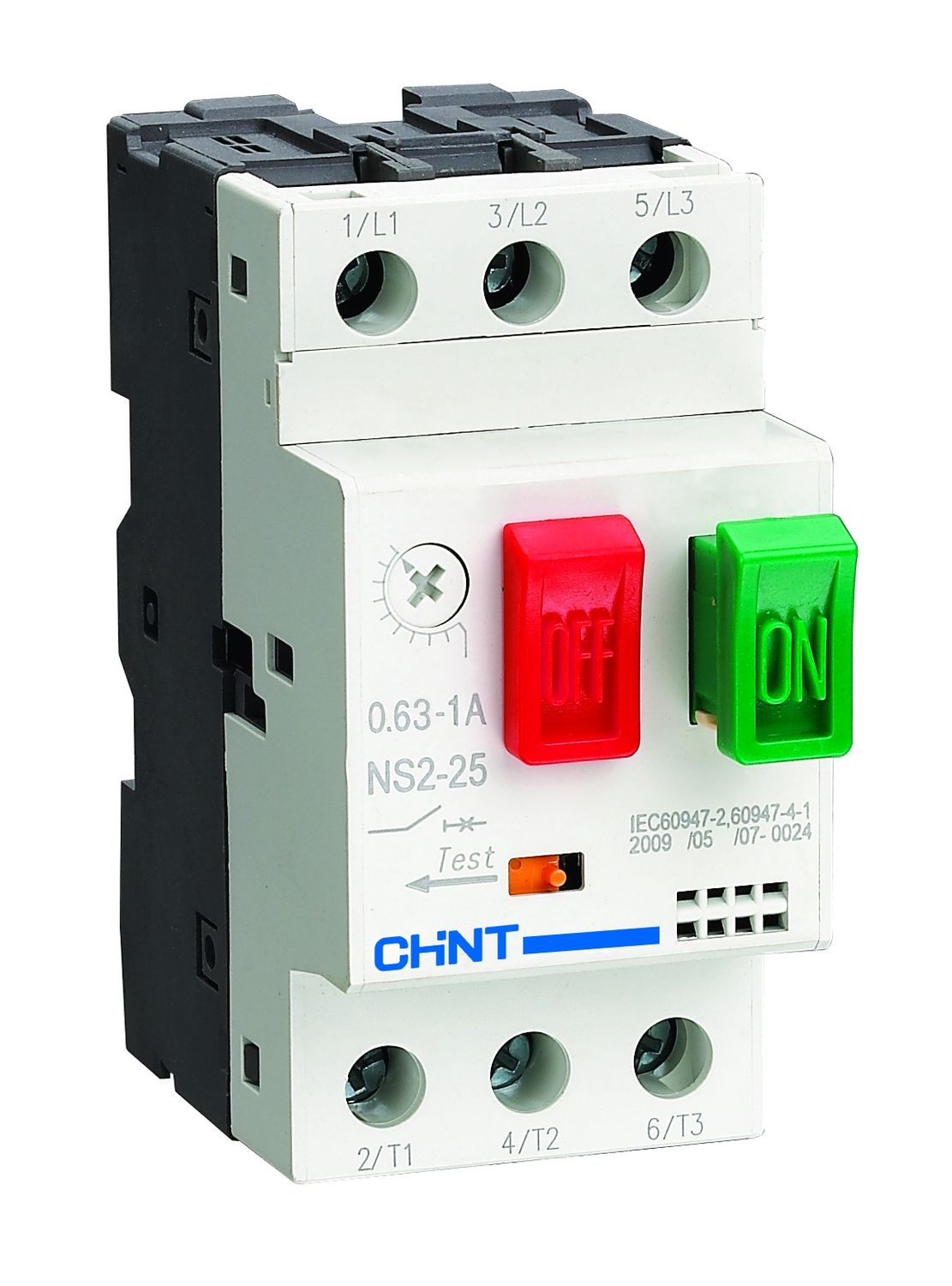
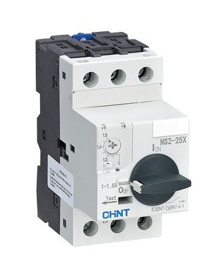
CHINT NS2 Manual Motor Starter (Button Type)
CHINT NS2 Manual Motor Starter (Button Type)
- The CHINT NS2 series, featuring models NS2-25, NS2-32, and NS2-80B, provides robust manual control and protection for 3-phase AC motors.
- These button-operated starters are designed for infrequent starting of motors up to 690V (NS2-25/32) or 415V (NS2-80B) and offer comprehensive protection against short circuits, overloads, and phase loss.
- Their versatility extends to use as distribution line protectors or isolators, making them a reliable choice for various industrial applications.
- They comply with IEC/EN 60947 standards and support a wide range of accessories for enhanced functionality.
Features
-
Manual Pushbutton Operation (ON/OFF/Test)
-
Adjustable Thermal Overload Protection (Wide setting ranges)
-
Instantaneous Short-Circuit Protection
-
Phase Loss (Phase Failure) Sensitivity
-
Suitable for AC-3 Motor Duty
-
Rated Operational Voltage up to 690V AC (NS2-25/32) / 415V AC (NS2-80B)
-
Trip Class 10/10A
-
Ambient Temperature Compensation
-
Can be used for Distribution Line Protection or as an Isolator
-
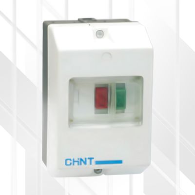
IP20 Protection (Standard), IP55 with optional enclosure
-
Compatible with a wide range of accessories (Auxiliary Contacts, Shunt/Undervoltage Releases, Enclosures)
-
Compliant with IEC/EN 60947-2 and IEC/EN 60947-4-1
-
Certifications including CE, EAC, UL (check specific model/region)
Benefits
-
Reliable Motor Protection: Safeguards motors from common electrical faults (overload, short circuit, phase loss), extending motor life and reducing downtime.
-
Enhanced Safety: Provides manual isolation capability and clear ON/OFF indication. Phase loss protection prevents motor damage from single-phasing.
-
Precise Settings: Adjustable thermal release allows fine-tuning protection to match specific motor characteristics, preventing nuisance tripping and ensuring optimal safeguarding.
-
Versatile Application: Suitable not only for motor control but also for protecting distribution lines and serving as a manual disconnect switch.
-
Simple Operation: Clear pushbutton controls make starting, stopping, and testing straightforward.
-
Expandable Functionality: Easily integrates with auxiliary contacts for remote signaling/interlocking, and shunt/undervoltage releases for remote or automated tripping.
-
Compliance Assurance: Meets international standards for safety and performance.
Technical Specifications
General Environmental & Operational Parameters:
-
Ambient Temperature: -5°C to +40°C (Average over 24h ≤ +35°C)
-
Relative Humidity: ≤ 50% at +40°C; up to 90% at +20°C
-
Altitude: ≤ 2000m (derating may be required above 2000m)
-
Pollution Degree: 3
-
Installation Category: III
-
Rated Frequency: 50/60 Hz
-
Rated Insulation Voltage (Ui): 690V
-
Rated Impulse Withstand Voltage (Uimp): 8kV (NS2-25/32), 6kV (NS2-80B)
-
Duty: Continuous / Long Term / Eight-hour day
-
Enclosure Protection: IP20 (Unit), IP55 (with NS2-MC/MC01/WPB-1 Box)
-
Max Operation Frequency: ≤ 30 times/hour (NS2-25/32), ≤ 25 times/hour (NS2-80B)
-
Standards: IEC/EN 60947-2, IEC/EN 60947-4-1
Model-Specific Details
| Model | Setting Current Range (A) | Motor Rating AC3 (400V) |
|---|---|---|
| NS2-25 | 0.25-0.4 | 0.09kW |
| NS2-25 | 0.4-0.63 | 0.18kW |
| NS2-25 | 0.63-1 | 0.25kW |
| NS2-25 | 1-1.6 | 0.37 / 0.55kW |
| NS2-25 | 1.6-2.5 | 0.75kW |
| NS2-25 | 2.5-4 | 1.1 / 1.5kW |
| NS2-25 | 4-6.3 | 2.2kW |
| NS2-25 | 6-10 | 4kW |
| NS2-25 | 9-14 | 5.5kW |
| NS2-25 | 13-18 | 7.5kW |
| NS2-25 | 17-23 | 11kW |
| NS2-25 | 20-25 | 11kW |
| NS2-32 | 24-32 | 15kW |
| NS2-80B | 25-40 | 15/18.5kW |
| NS2-80B | 40-63 | 22/30kW |
| NS2-80B | 56-80 | 37.5/45kW |
Wiring & Terminals:
-
Conductor Cross-Sectional Area:
-
NS2-25/32: 1 - 6 mm² (Refer to Table 7 in manual for specific current ranges)
-
NS2-80B: 4 - 25 mm² (Refer to Table 3 in manual for specific current ranges)
-
-
Strip Length: 10 mm (NS2-25/32), 15 mm (NS2-80B)
-
Max Conductors per Terminal: 2 (NS2-25/32), 2 (NS2-80B - Note: NS2-80 manual says 1)
-
Terminal Screw Size: M4 (NS2-25/32), M8 (NS2-80B)
-
Tightening Torque: 1.7 N.m (NS2-25/32), 6 N.m (NS2-80B)
Auxiliary Contact Details (Common Types):
-
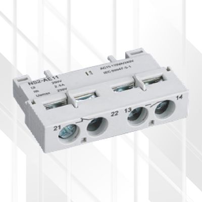
NS2-AE11/AE20 (Front): Ui=250V, Ith=2.5A, Uimp=2.5kV. AC-15: 0.5A@230/240V. DC-13: 0.15A@60V.
-
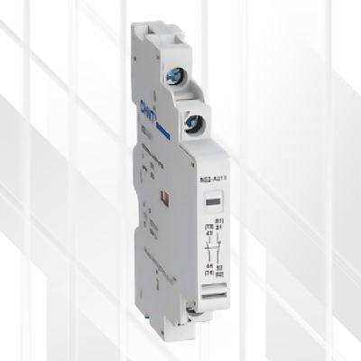
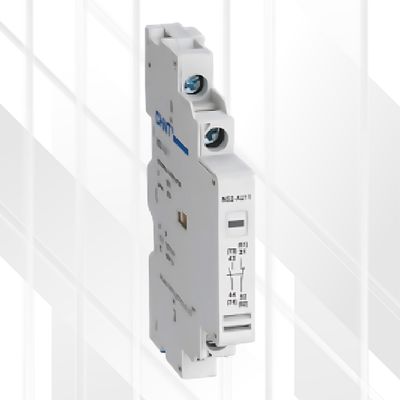
NS2-AU11/AU20 (Side): Ui=690V, Ith=6A, Uimp=4kV. AC-15: 3.3A@230/240V, 2.2A@380/415V. DC-13: 0.5A@220V. (Specific ratings may vary for NS2-80 designated accessories)
Find The Accessories:
- CHINT Front Mount Auxiliary Contact 1NO+1NC
- CHINT Side Mount Auxiliary Contact 1NO+1NC (NS2-25)
- CHINT Side Mount Auxiliary Contact 1NO+1NC (NS2-80B)
- CHINT Enclosure Surface for Starter NS2-25
Ideal Use
-
Direct-on-line (DOL) starting and protection of 3-phase asynchronous motors.
-
Industrial control panels for machinery (pumps, fans, conveyors, machine tools).
-
Agricultural applications.
-
HVAC systems.
-
Protection of electrical distribution circuits.
-
Manual isolation of loads.
Tips
-
Installation: Must be performed by qualified professional technicians. Ensure power is OFF during installation and maintenance. Avoid damp, condensed, flammable, or explosive environments. Mount vertically (max inclination 5°). Ensure installation site is free from strong shock or vibration.
-
Wiring: Select appropriate conductor size based on the operating current (refer to tables in the user manual). Strip wire to the correct length (10mm or 15mm). Tighten terminal screws to the specified torque (1.7 Nm or 6 Nm) to ensure a secure connection.
-
Adjustment: Set the thermal overload current dial according to the motor's full load ampere (FLA) rating. Use the TEST button after installation to verify correct tripping operation.
-
Backup Protection: If the prospective short-circuit current at the installation point exceeds the starter's Icu rating, coordinated backup protection (fuses or circuit breaker) is required. Refer to the manual's backup fuse tables (e.g., Table 8 for NS2-25/32, Table 4 for NS2-80B) for appropriate ratings (aM or gG/gL types).
-
Maintenance: Keep the starter clean from dust. Periodically (e.g., every six months) conduct functional tests and check terminal tightness.
-
Handling: Handle the starter carefully; avoid impacts or using cranes for handling, which could damage the unit or alter its protection characteristics.
-
Troubleshooting: Consult the troubleshooting guide in the user manual for issues like premature tripping (check setting, vibration, wire size, frequency) or failure to operate (check setting, wire size).
