CHINT Front Mount Auxiliary Contact 1NO+1NC
CHINT Front Mount Auxiliary Contact 1NO+1NC
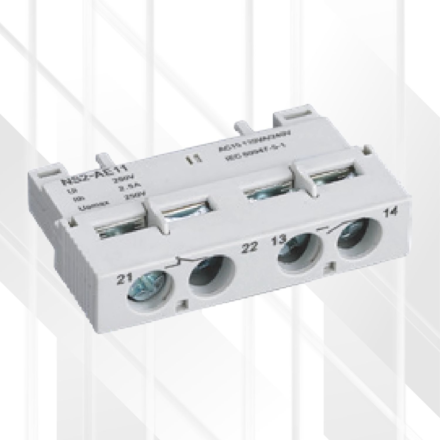
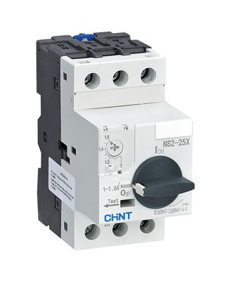
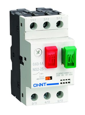
- The CHINT AUX-NS2-AE11 is a front-mounting auxiliary contact block designed for use across the NS2 series manual motor starters (including NS2-25, NS2-32, NS2-80, and NS2-80B variants).
- This compact accessory easily attaches to the front face of the starter, providing one Normally Open (1NO) and one Normally Closed (1NC) contact.
- These contacts operate synchronously with the starter's main contacts, offering a convenient way to integrate the starter's status into control circuits for signaling or interlocking purposes, especially where side mounting space is limited.
Features
-
Contact Configuration: 1NO + 1NC
-
Mounting Type: Front Mount / Front Hanging
-
Compatibility: Broadly compatible with NS2 series starters (NS2-25, NS2-32, NS2-80, NS2-80B families)
-
Easy Snap-On Installation to the starter's front face
-
Provides Electrically Isolated Contacts for control voltage circuits
Benefits
-
Space-Saving Design: Mounts on the front, ideal for installations with limited side clearance.
-
Remote Status Indication: Enables external monitoring of the starter's ON/OFF state via indicator lights or PLC inputs.
-
Control Circuit Interlocking: Allows for creating safety or sequential logic based on the starter's position.
-
Simple Integration: Easily adds signaling capability to manual starters for basic automation or monitoring.
-
Versatile Contacts: Provides both NO and NC states to suit different control circuit requirements.
Technical Specifications
-
Model: AUX-NS2-AE11 (Corresponds to generic type NS2-AE11)
-
Contact Configuration: 1 Normally Open + 1 Normally Closed
-
Rated Insulation Voltage (Ui): 250V
-
Conventional Thermal Current (Ith): 2.5A
-
Rated Impulse Withstand Voltage (Uimp): 2.5kV
-
Rated Operational Current (Ie) & Voltage (Ue):
-
AC-15: 0.5A @ 230/240V
-
DC-13: 0.15A @ 60V
-
-
Terminal Markings (Typical): 13-14 (NO), 21-22 (NC)
-
Standards: Conforms to auxiliary contact requirements within IEC/EN 60947 standards.
-
Compatibility: NS2-25, NS2-25X, NS2-32, NS2-32X, NS2-32H, NS2-80, NS2-80B
Ideal Use
-
Adding starter status feedback in control panels where side space is restricted.
-
Basic interlocking schemes involving NS2 starters.
-
Driving low-power indicator lamps or relay coils based on starter status.
-
Connecting NS2 starter status to PLC digital inputs.
Tips
-
Installation: Ensure the motor starter is de-energized. Align the AE11 block with the front mounting features/slots on the NS2 starter and press firmly until it securely clips into place. Refer to relevant assembly diagrams (e.g., Fig 4 for NS2-80, Fig 9 for NS2-25/32/32H). For some models, a screwdriver might be needed to manipulate a central slot during fitting.
-
Wiring: Connect control wires to the designated terminals (13-14 for NO, 21-22 for NC). Use appropriate wire gauge for control circuits and ensure terminals are tightened properly.
-
Testing: After installation, manually operate the starter (if safe) and verify the auxiliary contacts change state correctly using a continuity tester or multimeter. Check reliable mechanical coupling between the starter and accessory mechanism.
